This article is from Nexen, a partner of DIRECTPNEUMATICS.COM.
Seven Reasons – A Comparative Analysis
Air Champ® vs. Electric:
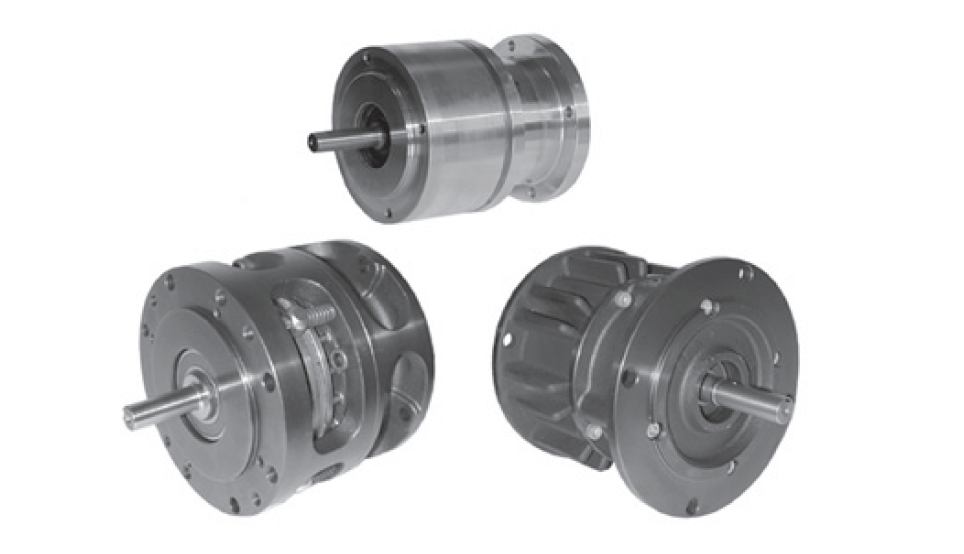
As the result of tests conducted by an independent laboratory, Nexen Group, Inc. identified seven key performance-related and cost-saving advantages of air-actuated clutch-brakes over electric units of comparable size. The tests were conducted by Huntingdon Engineering & Environmental, Inc. of St. Paul, Minnesota. Units tested were the Nexen Air Champ FMCBE-625 air clutch-brake and a comparable electric clutch-brake.
Advantages
- Response Time
- Torque Output
- Facing Life Comparison
- Thermal Horsepower
- Repair Costs
- Energy Consumption
- Unit Cost Savings
Air Champ® vs. Electric: Seven Comparison Points
- Response Time: Response time is the increment of time in seconds from the time the power is turned on or off at the control valve, or power supply, to the time the clutch or brake responds with (full load) torque, or disengages and the torque begins to decay. The time to 100% clutch torque for the air clutch was 40% faster than for the electric clutch. The time to zero torque (brake on) for the air clutch was 42% faster than for the electric.
- Torque Output: Tests focused on the torque output of NEMA 56 C-flanged air and electric clutch-brakes. The electric clutch transmitted only 54% of its rated torque. In comparison, the Nexen clutch transmitted up to 145% more torque under the same conditions, because it operated at a lower temperature. The higher operating temperature of the electric clutch affected torque fade, as well.
- Facing Life Comparison: The estimated facing life of air and electric units were determined in a calculation using the 1) volume of usable facing material, 2) friction materials wear rate, 3) work energy capacity, and 4) kinetic energy-per-cycle for a specific application. The results indicated that the Nexen clutch-brake had considerably more available friction facing volume, which translates into more horsepower-hours of work. While the friction facings on the Nexen unit were worn away partially, they still had sufficient material left to create the required friction against the facings to start or stop the load on the output shaft. The friction facings on the electric unit, on the other hand, were worn so far down that there was metal-to-metal contact.
- Thermal Horsepower: The test also revealed that the air clutch-brake consistently operated at lower temperatures compared to the electric unit. Nexen’s FMCBE-625 model has a rated thermal horsepower of 0.14. A comparable electric unit has a rated thermal horsepower of 0.10.
- Repair Costs: A test to determine the number of cycles to failure was conducted, and the Nexen clutchbrake was the overwhelming winner, more than doubling the number of cycles achieved by the electric unit. Additionally, replacement part costs published by the manufacturers showed that the air unit is less expensive to repair.
Nexen engineers conducted additional analysis to acquire comparative data on Energy Consumption and Unit Cost Savings. Here’s what they found:
- Energy Consumption: Using Friction Facing Life comparison information gathered in a conveyor system application, along with power consumption data published in the electric clutch-brake manufacturer’s catalog, it was discovered that the electric unit coil consumed 2.5 times more energy than the compressor that provided air to the Nexen Air Champ.
- Unit Cost Savings: Air Champ clutch-brakes cost up to 10% less than comparable electric units.
Introduction
As an international manufacturer of industrial power transmission brakes, clutches and clutch-brakes, Nexen leads the industry in innovation. Since 1951, our Engineering, Research and Development Teams have designed and tested products with one motivation in mind – to introduce quality products that help our customers reduce costs and increase productivity.
Our products are continually evaluated and updated, and new products designed to meet the demands in the marketplace. With the introduction of the first air-actuated brakes on the market, Air Champ®, Nexen has set the highest standard for optimal brake and clutch performance in the industry.
For decades, we have been promoting the benefits of these air-engaged clutches and brakes. Yet some people in the industry may still perceive electrically-actuated brakes as more effective, based on the fact that electricity is simple and convenient to operate. We agree electrically-actuated clutches/brakes are simple, but compared to air- actuated clutches/brakes, they don’t measure up in terms of efficiency or cost-effectiveness.
In fact, when you look at life performance, air-engaged clutches-brakes, come out way ahead. They typically have more than twice the life cycle of electrical clutches-brakes.
This document contains the actual performance results of a test conducted by an independent testing lab, between air-actuated and electrically actuated clutch-brakes. It gives comparative data in the following areas:
• Response Time
• Clutch and Brake Overlap
• Torque Output and Fade
• Friction Facing Life
• Electrical Energy Consumption
• Overall Power Consumption
The results clearly show that air-actuated clutch-brakes outperform electric clutch-brakes, and offer superior performance. In fact, Air Champ® clutch-brakes typically have twice the friction facing life cycle of electrical.
Our objective here is to give you a clear understanding of why air-actuated clutches and brakes work so well in the industry. Next time you’re asked to explain performance benefits of air over electric, you’ll have the facts.
Get the word out, because Nexen air-actuated clutches-brakes perform better than any other clutch-brake in the industry.
The Air Advantage
Air-engaged clutch-brakes are more efficient and economical to operate than similarly sized electric clutch-brakes because of one important reason – air-engaged clutch-brakes generate less heat during operation. Less heat allows greater torque transmission and efficiency. The greater thermal capacity of air-engaged clutch-brakes gives them longer operating life. Since more work is done with an air-engaged clutch-brake, air actuation proves to be more cost effective. It also costs less to run an air compressor than to operate an electric clutch-brake. Nexen Air Champ products have simple designs and fewer parts than electric clutch-brakes. These facts represent a significant savings (up to 80% over electric clutch-brakes) and lower costs for air-engaged clutch-brake users.
The Tests: Nexen FMCBE-625 vs. An Electric Clutch-Brake RESPONSE TIME
The following test was conducted under controlled test tab conditions. The two products tested were Nexen’s FMCBE-625 and a popular electrically-actuated clutch-brake. The first area we tested was response time.
Specifically, response time is the increment of time in seconds from the time power is turned on or off at the control valve, or power supply, to the time the clutch or brake responds with 100% torque, or disengages and the torque begins to decay.
For air-engaged units, the size of the control valve is a contributing factor to the response time value. A valve with a higher flow capability, or Cv factor, is desired for faster response time.
The derivation of response time data for a specific clutch-brake and control valve is typically measured under controlled test-lab conditions. The Nexen unit was controlled with a 4-way valve and with quick exhaust valves installed in the air inlets.
The electric unit was connected to a standard 90 volt power supply.
In a Nexen test, the time to 100% clutch torque was 72 milliseconds for the air clutch and 102 milliseconds for the electric clutch. The time to zero torque (brake on) was 56 milliseconds for the air brake and 80 milliseconds for the electric brake.
The air-engaged unit is faster partly due to its ability to bring the load up to speed with less slip at the friction interface.
Figure 1. Typical Comparison of Response Times.

Figure 2. Response Time Comparison.

Clutch and Brake Overlap
Overlap is a momentary time interval at the beginning of the clutch torque rise when the brake torque has not totally decayed. (See Figure 3.)
In air-engaged units having separate cylinders for the clutch and the brake, the tendency of overlap occurs because full supply pressure forces air into one cylinder at the same time the pressure in the other cylinder is pushing the air out the exhaust. In air-engaged units, this condition is controlled with quick exhaust valves located at the air inlet ports.
Electric clutch-brakes apply coil suppression techniques to control overlap. Coil suppression is defined as the use of a diode to direct the flow of reverse current to ground. Without suppression in the control circuit, an arc results from the strength of this current flow, resulting in simultaneous clutch-brake engagement. Even with coil suppression, a small amount of overlap can occur.
The difference between Nexen’s FMCBE and the electric clutch-brake is that Nexen is designed with only one piston which totally eliminates the possibility of overlap.
With Nexen’s FMCBE it is physically impossible to have a simultaneous clutch-brake engagement because the piston shifts one direction to engage the clutch and the other direction to engage the brake.
Figure 3. Clutch and Brake Overlap.

Next, we compared the torque output of electric clutches. Figure 4a shows that an electric clutch which ran 1,000 rpm, or 2,000 fpm, transmitted only 60% of its rated torque.
Figure 4a. Torque Fade Chart.

In comparison, the pneumatic clutch transmitted 35 to 40% more torque under the same conditions because it operated at a lower temperature. Note the dramatic drop in the electric unit torque when the speed increased.
The advantage of this kind of performance characteristic in the air-engaged clutch is that smaller air units can be used in place of larger electric units.
Also note the difference between the rated static torque and measured static torque in Nexen’s and electric clutch- brakes.
(Figure 4b)
Figure 4b. Empirical Data From Huntingdon Test.

As with torque output, the torque fade differs substantially between air and electrically-actuated clutch-brake performance.
All friction clutches and brakes slip during engagement. Some of the kinetic energy produced during slip converts to heat at the dynamic interface. This heat has a negative effect on clutch-brake performance because the friction lining’s coefficient of friction goes down when the temperature elevates, resulting in a torque decrease. This is known as “torque fade.”
Electrically-actuated clutches are engaged by continuously passing an electrical current through an electromagnetic coil. This current elevates the temperature of the entire unit even before any work is done.
However, air-engaged brakes are engaged with static, pressurized air contained in a cylinder. Static air maintains a constant force. Consequently, little energy is consumed.
In Figure 5, we see that excess heat greatly reduces the performance of clutches and brakes. The more heat that is introduced, either by friction or an electrical coil, the more limited the clutch or brake’s ability to deliver torque. In the center graph, note that the coefficient of friction begins to gradually decrease at 500° F. (Shown to explain the heat effect on a typical friction material.)
Figure 5. Heat Effect on the Coefficient of Friction.

These graphs are typical of data compiled from standard SAE tests (No. J661A) commonly known as “chase” tests. These tests are the benchmark by which all types of friction materials are evaluated.
Facing Life Comparison
Next we looked at the facing life differences between FMCBE-625 and the electric clutch-brake. To determine the estimated friction facing life we followed this procedure:
• First, find the volume of the usable facing material. The thickness of this material is usable to the mounting screw heads (Nexen) or backing plate (electric).
• Second, determine the friction material wear rate. (The wear rate of friction materials with a known coefficient of friction is determined under test conditions where speed and pressure are controlled and the material thickness loss is measured after a specific length of time.)
• Third, determine the work energy capacity. This capacity is the quantity or amount of energy that can be absorbed by the friction lining before it becomes consumed or worn away.
• And last, calculate the energy per cycle for a specific application. This is the amount of energy generated each time the clutch or brake is engaged. It is an estimate based on the size of the inertia load and the speed at which the load is applied.
The maximum number of cycles that can be applied before the lining is consumed is calculated by dividing the work energy capacity by the energy per cycle. See Figure 6.
Figure 6. Facing Life Derivation.

Figure 7. Facing Life Example.
Conveyor System Application
For a head to head analysis of pneumatic vs electric clutch-brakes the Nexen FMCBE-625 was compared to a comparable electric clutch-brake in a typical conveyor system application. They were subjected to the same set of operating criteria and calculated how each unit would perform under identical conditions.
The type of application is called a cyclic start-stop. The clutch-brake in the drive system positions boxes on a conveyor as they move under a hopper which fills the boxes with a product. A box is positioned under the hopper every second. For this, we used the following as our operating criteria:
• The system reflected inertia including the conveyor inertia, drum and pulley inertia and the clutch-brake inertia.
(Note: The inertia is called reflected because of the speed changes from the motor to the clutch-brake location.)
• The speed at the clutch-brake location.
• The energy per cycle.
• The cycle rate.
• The maximum number of cycles.
Figure 8a. Conveyor System Application.

Note: The maximum number of cycles shown here is the number calculated for Nexen’s FMCBE-625 operating under these exact criteria.
For conveyor systems, the data required to estimate the system inertia is:
• The weight (W) of the conveyor Load.
• The velocity (V), or speed of the conveyor in meters per minute.
• The speed (N) in rpm at the clutch-brake.
• This particular conveyor has a headstock drum driven by a pulley. The inertia of these parts is estimated using the weight and diameter of each component.
• The total inertia that the clutch-brake must start and stop every second is the conveyor load inertia, the headstock inertia and the clutch-brake inertia added together.
For a mathematical breakdown of a cyclic start-stop application see Figure 8b below.
Figure 8b. Example.

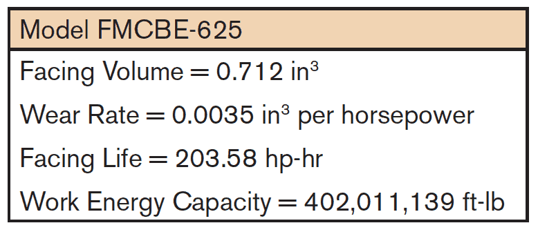
The calculated torque requirement for the application is 49 in-Ibs. An FMCBE-625, set at 30 psi provides the required torque with a 1.5 service factor. Checking the thermal horsepower requirement, we see that the energy per cycle is 38.56 ft-Ibs. The calculated thermal horsepower absorbed by the clutch brake is 0.07. An FMCBE-625 has a rated thermal horsepower of 0.14. A comparable electric unit has a rated thermal horsepower of 0.10.
Facing Life Comparison
With the load and operating characteristics of our example application, we then compared the friction facing life of Nexen’s clutch-brake to the electric clutch-brake.
Figure 9. Facing Life Comparison.

The Nexen unit has considerably more available facing volume, which translates into more horsepower-hours.
The comparative charts below show how we applied the mathematical steps explained earlier to both the Nexen FMCBE-625 and the electric clutch-brake.
Figure 10a. The Nexen FMCBE-625 Friction Facing.

Figure 10b. Electric Clutch-Brake Friction Facing.

The energy absorbed per cycle by the clutch-brakes when applied to the conveyor system was 38.56 ft. lbs. Dividing the work energy capacity of the friction material by the energy per cycle gave us the maximum number of cycles that each clutch-brake is capable of before replacement is necessary.
Life expectancy in hours was determined by dividing the maximum number of cycles by the cycles per hour.
Life expectancy in days was determined by dividing the number of life expectancy hours by the number of operating hours.
Electrical Energy Consumed
Using the friction facing comparisons we determined the amount of electrical energy required to operate an air-engaged unit vs. an electrically-engaged unit.
First, we compared the amount of electrical energy consumed by a compressor used to produce the 30 psi required of the clutch-brake with the electrical energy consumed by the electric unit’s coil.
The total amount of free (or uncompressed) air required was 0.090 SCFM.
Figure 11. Volume of Free Air Consumed Per Cycle.

Next, we looked at the air-engaged unit to determine the amount of free air consumed per cycle and the horsepower to compress this free air. We converted compressed air to free (uncompressed) air based on 14.7 psi of atmospheric pressure (or absolute pressure).
The data below shows the procedure for calculating the amount of free air (SCFM, standard cubic feet per minute) consumed by the clutch-brake in the conveyor application.
Figure 12.
 The horsepower to drive a single-stage compressor to compress 0.090 SCFM of free air to 30 psi is taken from the table below:
Figure 13.
![]()
* HP to compress 1 SCFM from 0 PSIG to the values shown.
NOTE: The power required from other types of compressors of the same number of stages will be related to these values as the efficiency of the other compressor is to the assumed 85 percent efficiency used for these tables. The table is taken from a fluid power data book published by the “Fluid Power Distributors Association.”At 30 psi the compressor factor is 0.095.
The horsepower to compress 0.090 SCFM to 30 psi = 0.095 x 0.090 = 0.00855 Horsepower.
To arrive at the actual power consumption of the air-engaged clutch-brake, we multiplied the horsepower that operates the compressor by 745.7. The result was 6.38 watts.
In contrast, the electric clutch-brake power consumption, published in the manufacturer’s catalog was 18 watts.
Figure 14. Power Consumption.

Since electrical energy is purchased in kilowatt-hours, we converted watts to kilowatts or kilowatt-hours by dividing the watts by 1,000.
OUR FINAL RESULTS: IN THE CONVEYOR APPLICATION, THE ELECTRICAL UNIT COIL CONSUMED 2.5 TIMES MORE ENERGY THAN THE COMPRESSOR THAT PROVIDED AIR TO THE CLUTCH-BRAKE.
Figure 15. Electrical Energy Consumed.

The electric unit consumes 2.5 times more energy than an air unit in our example application.
Failure Mode
Nexen Clutch-Brake
Failure of output bearing. Unit still picking-up and stopping output shaft load. Maximum cycles, cycling of clutch-brake terminated.
Electric Clutch-Brake
Fails to pick-up output shaft load occasionally.
Total Benefits
In the final analysis, when comparing the Nexen FMCBE-625 and the electric clutch-brake in similar applications, the measured torque (in inch-pounds) is higher in the FMCBE-625.
The air-powered clutch-brake response is faster and the measured thermal horsepower is better.
Figure 16. Product Comparison. Empirical Data from Huntingdon Test. Product: Totally Enclosed 625 Clutch-Brake.

Based on the entire test analysis results, the benefits of air-actuated clutch-brakes over electrically actuated clutch-brakes are:
- Up to 30 percent faster response time.
- Up to 40 percent more dynamic torque.
- Up to 6 times longer friction facing life.
- Up to 2.5 times less energy (electrical) consumption.
- Up to 30 percent more thermal horsepower.
- Up to 10 percent savings in unit cost.
- Up to 80 percent savings in repair costs.
No other clutch-brake manufacturer can offer you innovation like Nexen. With the Nexen Air Champ® line, you can improve your business through efficient production and efficient costs. It just works better for you.
But product efficiency is just one example of Nexen’s leadership in the industry. We have an ongoing commitment to use the latest research, technology and manufacturing methods to produce products that offer the best performance and applications in the world.
We intend to stay ahead of the game. As we do, we will always keep you educated and informed of our innovations designed with your production needs in mind.
www.nexengroup.com
In accordance with Nexen’s established policy of constant product improvement, the specifications contained in this document are subject to change without notice. Technical data listed in this document are based on the latest information available at the time of printing and are also subject to change without notice. For current information, please consult www.nexengroup.com.
Nexen Group, Inc.
560 Oak Grove Parkway
Vadnais Heights, MN 55127
(800) 843-7445
Fax: (651) 286-1099
www.nexengroup.com
Nexen has sales offices throughout the United States, Europe, Japan, and Australia.
ISO 9001 Certified
©2011 Nexen Group, Inc.