A whitepaper written by FESTO
Particles, water, and oils in compressed air reduce the service life and functionality of components and systems. They also impair productivity and energy efficiency. Proper preparation, on the other hand, significantly increases process and product reliability, and it increases the availability of your system.
This white paper contains information on:
- How air preparation improves the process reliability, machine availability, and service life of all components
- The criteria for choosing the best service unit and which physical principles need to be taken into account
- The functional principles and areas of application of the different service units
- How to configure a service unit for optimum performance
1. Compressed air preparation in the system
Compressed air is an essential medium for any modern production company. And with good reason: compressed air can be used in an unparalleled range of applications, and combines speed, power, precision, and safe handling. However, before these benefits can be put to use moving pneumatic components, several preparatory steps need to be followed.
At the start of every compressed air system is a compressor. The compressed air it generates is prepared using a refrigeration dryer. There is usually a compressed air reservoir just upstream or downstream of the refrigeration dryer. This is designed to compensate for fluctuations in consumption. The compressed air is channeled via tubes to the decentralized air preparation stage.
It is this stage which is the subject of this white paper, which will offer a general description of the following functions: switching on, building up pressure, filtering, regulating, drying, and oiling. Finally, the prepared compressed air is supplied to the machine and used to actuate the application.

2. Compressed air preparation
 – an essential factor in improving the process reliability, machine availability, and service life of all components
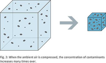
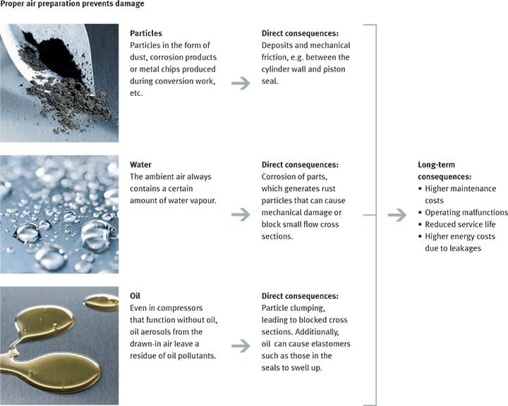
Did you know? One cubic meter of unprepared ambient air contains a huge number of components that can impair operation.
These include:
- Dirt particles: up to 180 million between 0.01 µm and 100 µm (typical particle sizes [µm]: viruses 0.01; tobacco smoke 0.1; water vapour 5 … 80; hair 40 … 150)
- Water: dependent on temperature, up to 80 g at 50°C
- Oil: up to 0.03 mg
- Chemical contaminants: e. g. lead, cadmium, iron, mercury, etc.
Compressed air preparation helps to minimize damage and its consequences. It is essential for the smooth functioning of pneumatic components and for process reliability in production processes.
On top of this, different industry segments and specialist applications also have other requirements regarding the quality of compressed air.
 3. Criteria for choosing the right service unit
Three main features characterize good air preparation for the consuming device: the right level of compressed air purity, a sufficient amount of compressed air, and a suitable level of pressure for the application in question. These features need to be taken into account when selecting a service unit.
Put simply:
- A suitable level of compressed air purity improves the service life and efficiency of the pneumatic system and allows it to be used in accordance with the applicable regulations, e.g. in the food industry.
- The right amount of compressed air: the correct flow rate is needed to achieve the specified cylinder piston travel speeds, for example.
- A level of pressure that is in line with demand will provide the force required to move the components and the workpieces.
3.1 Suitable compressed air purity for pneumatic components and specific applications
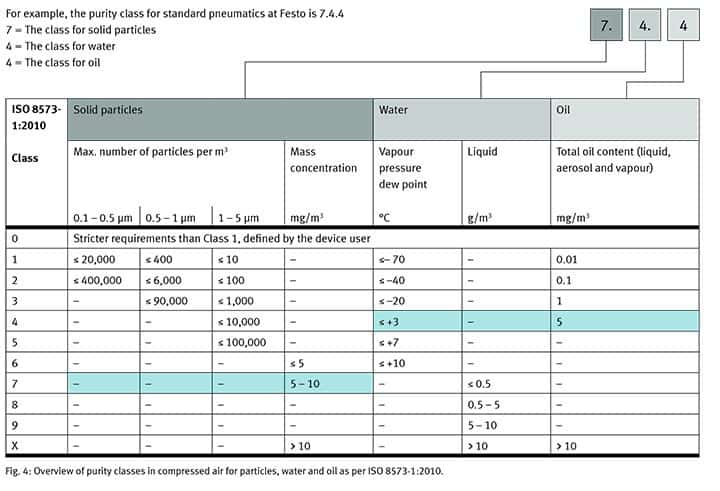
The compressed air purity is defined in the ISO 8573-1:2010 standard. Three criteria are used to determine the purity class of the air:
- Solid particles
- Water
- Oil
For each of these classes, the standard defines the maximum contaminant content that may be contained in the compressed air. The higher the class, the lower the required degree of purity. The required level of compressed air purity for pneumatic components such as valves and cylinders is specified by manufacturers.
Typical applications and their purity classes
Different applications require different levels of compressed air purity in order for the process to run smoothly. The table below reflects only practical experience and was drawn up based on the VDMA standard sheet 15390-1.
The values it contains are approximate, not absolute. Every application must be tested by the operator on an individual basis.
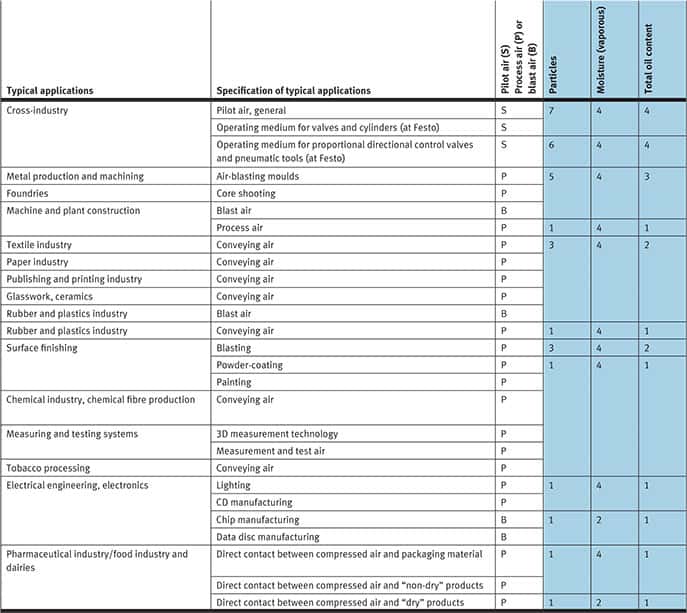
Explanation of terminology:
Pilot air is used to control valves, cylinders, grippers, etc., and does not come into direct contact with the products. Where there is contact, the compressed air is spread out over a suitable distance and diluted with normal compressed air. In such situations, it is important to consider to what extent the pilot air may have a negative impact on the process – e.g. when the pilot air is exhausted. If necessary, the purity class of the pilot air should be based on the purity class of the process air.
Blast air is used to clean machines and workpieces. It comes into direct contact with the product during machining and processing.
Process air is a medium that is either physically or chemically involved in machining or processing. It can also be used to transport products. This means that
it comes into direct contact with the product during machining and processing.
Determining purity classes:
The particles discussed in this white paper belong to classes 7, 6, 5, 3, and 1. When specifying the moisture, the pressure dew point must be at least 10 K lower than the medium temperature. The oil classes in the VDMA standard sheet are used as a benchmark and must be observed.
Supplements to the applications:
If sterile packaging is required, the purity class specified in the table must be met and a sterile filter inserted downstream.
Note: some service units can be combined in order to reach a certain purity class. However, if the ambient air used to make compressed air is severely contaminated, the specified service units may need to be supplemented with others.
3.2 Sufficient amount of compressed air: sufficient flow rate [l/min] is a must
The application determines how a system builder configures a pneumatic machine. When doing this, it is important to remember that the technology and operating costs of a system are only at their optimum when every component receives a sufficient supply of compressed air.
The flow rates provided by service units are determined largely by the flow cross-sections and design. Put simply, provided the design is the same, the greater the dimensions of the service unit, the higher the flow rates. The flow rate also varies depending on the different functions of the devices. For example, filters provide natural resistance and usually limit the flow rate. If the proper service units are chosen for the application, but the system still fails to reach the required flow rate values,
the following criteria must be checked:
- Are the connection cross-sections too small?
- Are there disturbances caused by excessively long lines, branches or laying radii that are too small?
- Are there raw surfaces on the insides of the lines, or is there contamination in the lines?
- Are there any undiscovered leakages?
3.3 Pressure: the right operating pressure counts
 Every pneumatic consuming device is configured to its own optimum operating pressure range. If the operating pressure is too low, this will reduce the efficiency of the system, and often prevent it from functioning correctly. Excessive operating pressure increases wear of seals and other parts, increases energy consumption and generates an uncomfortable level of noise.
Potential pressure drops must therefore be factored into the calculations in order to attain the correct operating pressure. These pressure drops can be caused by:
- Consuming devices such as valves, filters, drying units, etc.
- Long lines, branches, unsuitable bending radii, rough inner surfaces and contamination in the lines
- Undiscovered leakages
These are the most common causes of insufficient flow rates.
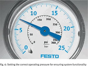 The permissible pressure for a service unit is determined by the housing material, adjusting springs, etc. Depending on the region, the pressure is specified using one of the following units of measurement: 1 bar = 0.1 MPa = 14.5 psi
In addition to these three main factors, various physical principles also need to be considered.
4. Important physical principles for choosing and connecting service units
Particles and oils in pneumatic systems can largely be observed irrespective of temperature and pressure. This does not apply to the third component, water.
Air humidity
 The ambient air always includes a certain amount of water vapor, which can be measured as absolute air humidity [g/m³]. If the temperature drops below a certain level or the air is highly compressed, some of this humidity will be output as condensate.
It is important to recognize this phenomenon and take it into account for air preparation. In the compressed air applications detailed here, the compression of the ambient air generally exceeds the maximum air humidity [g/m³], and condensate drips out. Even taking into account the air humidity of the local conditions, the choice of service unit remains the same. So in tropical countries, more condensate is produced during compressed air preparation than in continental climate zones.
- Absolute humidity [g/m³] is the amount of water actually contained in the normal ambient air.
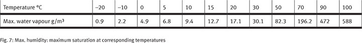
- Maximum humidity [g/m³] is the maximum amount of water vapor that can be absorbed by the air at a certain temperature.
- Relative humidity [%] is the ratio of absolute to maximum humidity.
For example: at a relative humidity of 100% and a temperature of 50°C, the air can contain a maximum of 82.3 g/m³.
Pressure dew point
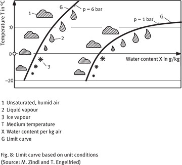 Knowing the pressure dew point is even more important for ensuring that the service unit is configured correctly. The pressure dew point defines the temperature to which compressed air can be cooled without the water in it condensing. The relative humidity is then 100%. If the temperature is below the pressure dew point is then 100%. If the temperature is below the pressure dew point increased, this condensate will remain and can lead to corrosion of components. This is why service units contain dryers that lower the pressure dew point.
1 Unsaturated, humid air
2 Liquid vapour
3 Ice vapour
T Medium temperature
X Water content per kg air
G Limit curve
5. Which service unit regulates what? An overview.
There is a good reason for the myriad of service units that are available. This section will explain how each component contributes towards ensuring perfect air preparation.
Manual or electric on/off valves
Open and close the system’s air supply. In order to avoid inadvertent movements or forces in a switched off the system, the valve exhausts as it closes.
Soft-start valve
These valves slowly build up pressure when the system is started up. They do not apply the full pressure until a certain point has been reached. This means that downstream devices such as cylinders are advanced slowly to their initial positions to prevent the material damage that can occur with a sudden movement.
- Pneumatic soft-start valves open fully as soon as 50% of the inlet pressure has been reached.
- Electric soft-start valves switch to full pressure at different points depending on the application, e.g. when downstream components have reached their end positions.
Water separators
Remove additional condensate from the compressed air lines. They are especially important when the compressor and service unit are far apart, or if there is a lot of condensate in the compressed air system. Water separators either take the form of centrifugal separators or use the coalescence principle. A centrifugal separator such as those made by Festo causes rotary motion in the air. The centrifugal forces to which the particles are subjected accelerate them in a radial, outward movement. Once they reach the outside, they flow off into the bowl. This process filters out water droplets and dust and dirt particles >50 µm. No maintenance is required for this process.
With the coalescence principle, on the other hand, the medium flows from the inside to the outside through a filter according to the fine filter principle. These filter cartridges must be replaced regularly. Like fine filters, their maximum flow rate must not be exceeded.
Filters
These are used to filter particles, condensate, and oil in compressed air, protect pneumatic components, and achieve specific purity classes.
 Coarse filters, or strainers, have a pore size of 5 to 40 µm. The medium flows through the filter cartridges from the outside to the inside; this is combined with the centrifugal separator principle.
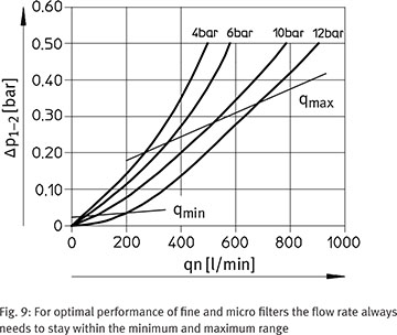
- Fine and microfilters can filter out particles smaller than 1 µm. The medium flows through the filter cartridges from the inside to the outside. Solid particles get stuck in the filter cartridge, clogging it up. Fluid particles, such as condensate or oil, coalesce or attach to larger droplets, which flow off and are caught in the filter bowl. When using these filters, it is essential to maintain the specified flow range. Increased consumption – e.g. due to the use of additional cylinders – can lead to the maximum flow rate being exceeded. As the flow rate increases, so does the flow velocity, and the pollutants that need to be filtered out are swept along with the flow instead. It is then no longer possible to guarantee the specified purity class. Likewise, if the minimum flow rate is not reached, the pollutants cannot be caught by the filter as intended. Maintaining the flow rate and if necessary, choosing products with larger dimensions can reduce the pressure drop from the filter.
- Activated carbon filters bond hydrocarbon residue odorants, flavorings, and oil vapors.
- Sterile filters ensure that air is sterile and free of germs
In terms of flow mechanics, filters provide resistance and often limit the flow rate of a service unit.
 Pressure regulators
Pressure regulators constantly control the operating pressure of a system and compensate for pressure fluctuations. Indirectly actuated regulators, the mainspring is set using a knob. This pushes the control piston down and allows free flow. Pressure regulators are a low-cost alternative to high-flow, upstream regulators. These regulate the piston or membrane using an air cushion.
If a service unit needs to supply different applications with different pressures, additional regulators can be used. With these, the pressure in the axial direction remains unchanged from p1 to p1 of the different regulators. The set pressure is output downstream via outlet port p2.
Drying units
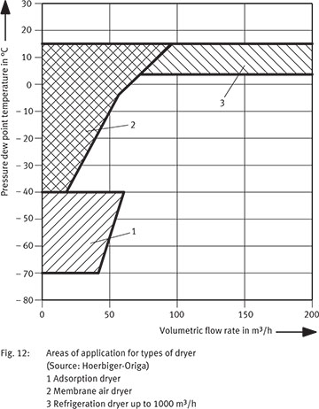
In practice, there are three different procedures that can be used to dry compressed air: adsorption dryer, membrane air dryer, and refrigeration dryer up to 1000 m³/h
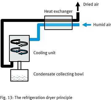 Refrigeration dryers
Generally speaking, a refrigeration dryer should be placed downstream of each compressor. The air is cooled to just above freezing in a cooling unit, and the condensate that falls off is drained away. In order to save on energy costs, heat is exchanged between the cold dried air and the warm air that still needs to be dried. The pressure dew point is then approx. 3 °C. Since the safety margin to the pressure dew point needs to be 10 K, this is sufficient for systems whose operating temperature never drops below 13 °C.
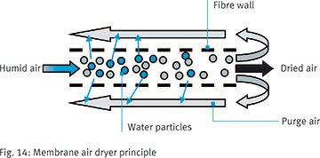
- Membrane air dryers
lower the pressure dew point. Membrane air dryers from Festo lower the pressure dew point by 20 K, for example. The air flows longitudinally through a bundle of parallel, hollow fibers. During this process, water vapor diffuses because of a partial pressure drop from the inside of the fibers to the outside. The vapor is drained out using purge air. Due to the purge of air, the maintenance-free dryer has a certain amount of constant bleed.
 Adsorption dryers
are used when pressure dew points of –70°C are required. The dryers use molecular forces to bond gas or vapor molecules to a drying agent. Since the drying agent is regenerative, two chambers are required: while drying takes place in one, in the other the drying agent has time for cold or warm regeneration. In devices with cold regeneration, such as those offered by Festo, some of the dried air is used to dry the adhesion agent. When warm regeneration is used, the water evaporates as heat is applied. The drying agent must be replaced regularly.
In a membrane and adsorption dryers, the higher the inlet pressure, the better the efficiency. The inlet pressure should therefore be as high as possible. In addition, a certain amount of caution is required with some connection materials. Hemp joints on piping, for example, are air-tight, but may still draw in water from the ambient air and channel it into the system.
Lubricators
where used in the past to lubricate downstream pneumatic components. This is no longer necessary thanks to the optimization of lubricating greases in valves and drives. However, as the saying goes, “oil it once and you’ll be oiling it forevermore”, because oils wash the lubricating greases out of the components. Note: excessive oiling can clog up silencers and other pneumatic elements.
Branching module
A branching module has more than two ports. It can be used as an intermediate or end outlet for various air purities, or as a support for auxiliary modules. The branching module can be ordered with or without a built-in non-return valve. This function prevents the return flow of oiled compressed air and other substances.
6. Extended functions:
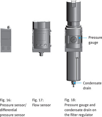
Pressure sensors
Monitor a set pressure to guarantee a specific work result, e.g. during tool clamping.
Differential pressure sensors
Measure the pressure drop when using fine and microfilters, for example. This allows the operator to define whether the filter cartridges should be replaced.
Flow sensors
Measure the flow rate and thus monitor the system’s energy requirements, for example.
Pressure gauges
Provide an analog pressure reading. Note: the pressure gauges used in service units may only be pressurized up to 2/3 of their display scale, otherwise the measurement cell will be damaged.
Condensate drain
Available in three variants as part of a filter, filter regulator, or water separator:
- Manual: condensate is drained manually
- Semi-automatic/normally open: opens as soon as the compressed air is shut off
- Fully-automatic/normally open: opens as soon as the compressed air is shut off or a specified level is reached Fully-automatic/normally closed: opens as soon as the compressed air is switched on and a specified level is reached
Trends and new technologies:
Safety valves MS..-SV.. with pressure build-up and exhaust function Two-channel safety valves, such as the MS6-SV-E to ISO 13849-1 from Festo, are used to build up pressure gently and exhaust safely and quickly.
Energy efficiency module MSE6-E2M
Energy efficiency modules, such as the MSE6-E2M from Festo, shut off the compressed air supply to the machine when the system is at a standstill – thus preventing additional waste as a result of possible leakages in the machine. Like the automatic stop-start function in modern cars, this cuts off the power supply during standstills. At the same time, it allows important system operating parameters, such as flow rate and pressure, to be monitored to ensure process reliability during production.
7. Combining service units correctly:
Which component goes where? A recommendation.
Note: there are different ways of putting together service units. The order of the components is primarily dependent on application-specific criteria. The diagram below illustrates one possible structure.
Service unit combinations for standard pneumatics tasks for operating valves and cylinders – basic components

1 Manual on/off valve
This separates the downstream units from the compressed air system so that they can be serviced. It is therefore generally the first device in a unit.
2 Filter regulator
This combines the functions of a filter and a regulator in a single device.
Strainer (coarse filter)
These are placed as far upstream as possible in the service unit so as to protect the downstream modules.
Pressure regulating valves/regulators
These regulate a defined pressure. In order to ensure that the machine is supplied with the pressure it needs for the application, the pressure drop downstream of the regulator should be kept as low as possible. Since the strainer causes a pressure drop, it is usually placed upstream of the regulator.
3 Electric on/off valve
This should be placed downstream of a strainer for its own protection. When using fine and microfilters, the on/off valve is usually placed upstream of the filters to make sure that any oils and particles from the valve are filtered out. The valve is also often placed downstream of the regulator so that the compressed air does not need to be channeled through the regulator when exhausting.
4 Soft-start valve
This is generally placed downstream of the electric on/off valve.
A soft-start valve must never be placed upstream of products with a fully or semi-automatic, normally open condensate drain, otherwise the compressed air will be constantly blasted through the condensate drain. This would prevent the pressure required to actuate the soft-start valve/close the condensate drain from being reached.
5 Branching module
There is no preferred installation position for this component. It can be placed either before or after the safety valve.
6 Lubricator
Wherever possible, lubricators should be placed directly upstream of the consuming device, so that the oil is not channeled through the system unnecessarily. Lubricators are often combined with a filter regulator. However, they should not be placed upstream of fine filters, microfilters, or flow sensors. Note: thanks to the optimization of lubricating greases in valves and drives, a lubricator is not usually required in modern systems. However, as the saying goes, “oil it once and you’ll be oiling it forevermore”, because oils wash the lubricating greases out of the components.
7 Water separator
When placed in the first position, these protect manual on/off valves from water and coarse dirt particles. In the second position, downstream of the manual on/off valve, they can be separated from the compressed air supply. This also allows the water separator to be serviced, e.g. the bowl to be cleaned.
8+9 Fine and microfilters
At Festo, there is always a 5 µm strainer upstream of these filters. They should generally be placed towards the end of the chain, as they filter out any particles and oils from the devices upstream of them.
10+11 Adsorption dryer and membrane air dryer
Adsorption dryer
Prefiltration may be required for some brands of adsorption dryers. Festo uses a 5 µm strainer and the micro 0.01 µm micro filter included in the scope of delivery, which protects the granules. A 1 µm fine filter is built into the adsorption dryer for post-filtering. For a better particle class, the 0.01 µm fine filter is placed downstream of the dryer, or an activated carbon filter for a better oil class.
Membrane air dryer
This requires prefiltration as defined by the manufacturer. Festo requires a minimum filtration of 5 µm and 0.01 µm. For a better oil class, the activated carbon filter is placed downstream of the dryer.
The membrane air dryer and adsorption dryer are usually placed downstream of the regulator. This allows you to use a filter regulator without needing the separate strainer and regulator modules, for example. However, dryers offer greater efficiency at higher inlet pressures. An inlet pressure of at least 6.9 bar is recommended for optimum dryer use. If the compressed air system meets this requirement but the regulator is still regulating a lower pressure, you should consider placing the regulator downstream of the dryer. However, the regulator may then channel particles and oil into the system. If a corresponding purity class is required, a 0.01 µm microfilter or activated carbon filter should be placed downstream of the regulator.
12 Activated carbon filter
Prefiltration may be required for some brands of activated carbon filters. At Festo, for example, there must always be a 5 µm strainer and a 0.01 µm filter upstream of these filters.
For monitoring and displaying pressure and flow rate
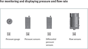 13 Pressure gauge
This can be placed anywhere on a service unit.
14+15 Pressure and differential pressure sensors
These can also be placed wherever the application requires.
16 Flow sensors
These are stand-alone service units that must not be placed directly downstream of a regulator or filter regulator. The vortices generated by these devices affect the sensor’s measurement accuracy. In addition, the Festo flow sensor also requires a 40 µm filter upstream of it for protection. Lubricators must never be placed upstream of the flow sensor.
Product trends for energy and safety
 17 Energy efficiency module
This is generally positioned decentrally, downstream of the service unit. However, since it has only one channel, the system connection remains reserved for the safety valve.
18 Safety valve with soft-start and exhaust function
The two-channel safety valve must always be installed at the end of the system where it cannot be influenced by downstream service units.
8. Tips for your air preparation
Tip 1
Get your air preparation up to speed. It is a worthwhile investment, and essential for a reliable production process. Air preparation that is tailored to your needs will significantly improve the service life of components and your system availability. Particles, water, and oils contained in the compressed air can lead to mechanical friction, corrosion, and clogging.
Tip 2
When choosing a service unit, always consider three factors: suitable compressed air purity, sufficient flow rate, and the correct pressure for your application.
Tip 3
Make sure that your pressure dew point is 10 K below your lowest ambient temperature. This will keep your system free of condensate and reduce component corrosion.
Tip 4
Remember that air preparation involves a number of different stages. As such, it covers a range of different modules: for switching on, building up pressure, filtering, regulating, drying, and oiling. These are used in different ways depending on the application.
Tip 5
In order to ensure optimum performance, arrange the components in your service unit according to the guidelines in Section 6. If in doubt, consult an expert to find out the best combination for you.
Publisher/author: Festo AG & Co. KG / Adeline Konzelmann- Air Supply Product Management
Technical Product Support: Milorad Garic, E-Mail: milorad.garic@festo.com www.festo.com
Brought to you by FESTO, a partner of DIRECTPNEUMATICS.COM
© Copyright 2015, Festo AG & Co. KG