A whitepaper written by Festo AG & Co. KG
A Comparison of Individual Valves and Valve Terminals
Individual valves or valve terminals – which is the most suitable option for actuating pneumatically automated process valves? What are the technological and economic differences between the two? We will use a cost comparison to compare and contrast the two options. And what are the differences in terms of commissioning? Which diagnostic options are available with valve terminals for reducing unscheduled downtime? These are the questions that will be examined in this article.
This white paper provides information on:
- Comparison of individual valves and valve terminal architectures
- Technological and economic differences
- Cost comparison
- Using valve terminals in safety instrumented systems (SIL)
- Practical examples
Introduction
Pneumatic automation has come a long way in recent years. Whereas in the past automation with individual valves mounted on the actuator was standard, nowadays high-performance valve terminals with integrated electrical inputs and outputs are available. Integrated controllers enable small automation tasks to be carried out in the field.
Thanks to SIL certification, valve terminals can also be used in safety instrumented systems. This means that safety circuits with a rating of up to SIL2 can be implemented using this technology.
Intelligence is moving into the field
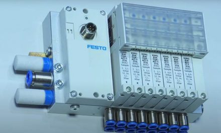
The valve terminal is at the heart of decentralized pneumatic automation. It facilitates the quick and easy setup of decentralized automation solutions. The valve terminal shown in figure 1 (Festo CPX/MPA) is completely modular. It can activate up to 64 solenoid coils and can process digital and analog electrical signals. Communication with higher-order automation systems takes place via a fieldbus. In addition, the valve terminal can be equipped with a controller so that parts of the system can be operated independently of a process control system
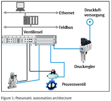 These components enable customized, consistent automation concepts to be created, from the process valve right up to the management level.
When doing so, it is important to use components that precisely match one another to ensure the optimal functioning of all the elements within the control sequence.
It is often the small details that cause problems: for example, signal transmission is delayed if the tubing or connectors have diameters that are either too large or too small or if they are made of materials that are not suitable for the application. Although the cost differences may be minimal at the initial investment stage, incorrect planning may become very expensive during system operation should a replacement be necessary.
Advantages of a decentralized pneumatic automation concept include:
- Flexibility thanks to the fieldbus, easy integration, and expandability
- Time savings resulting from simultaneous engineering of modules
- Safety thanks to autonomous pretesting of the modules
- Reduced installation effort
- Maximized system availability thanks to system diagnostics
In comparison with individual valve solutions, significant cost savings can be achieved when using valve terminals. This applies in particular to systems where many valves are positioned very close to each other. This is often the case in precision and specialized chemicals, biotechnology, and pharmaceuticals, food production, in filter systems, and in the digestion towers of municipal wastewater treatment facilities.
The situation in the chemical and petrochemical industries may be quite different as valves are often installed far apart. Below is a cost comparison to weigh valve terminal technology up against individual valve architecture.
Cost comparison – valve terminal versus individual valves in large systems
 Figure 2 shows an actual production system in the field of precision and specialized chemicals which will be used as a basis for comparison. It covers an area of roughly 20 by 20 meters, is 15 meters high, consists of four levels, and is used to produce raw materials for body care products and laundry detergent.
The system is controlled by approximately 100 pneumatically automated process valves – predominantly ball valves, poppet valves and butterfly valves with nominal sizes of 25 to 200.
The system is equipped with individual valves and limit switch boxes on the actuators or with a box containing an end-position feedback indicator and an integrated solenoid valve. Only the opening and closing valves have been taken into consideration for the cost comparison. The calculation is based on the control cabinets already included in the system.

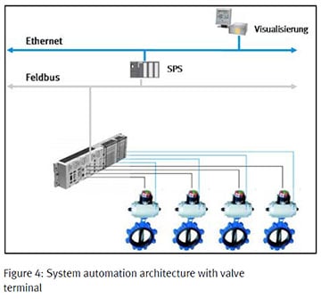
System automation with individual valves is shown in figure 3, and with valve terminals in figure 4. The individual valves are mounted directly on the valve actuators via a NAMUR interface. Individual valves and end-position sensors are coupled to the fieldbus via remote I/O. The valve terminal architecture is simpler: a fieldbus connection, remote I/O, and solenoid valves form one unit at the decentralized control level. When using valve terminal technology as opposed to the individual valve concept, the binary output at the remote I/O for controlling the individual valves is eliminated, together with the necessary wiring. The valve terminals have been positioned within the system so that the process requirements for the opening and closing times of the process valves are fulfilled.
 The following assumptions have also been taken into consideration for the calculation:
- Installation effort/connection costs for the unit including individual valves with remote I/O are compared with the unit including a CPX/MPA valve terminal.
- A multi-core cable is used to control the solenoid valve and the sensor box in the individual valve solution. When using valve terminals only the number of cores in the cable is reduced, and the cost difference is negligible in this case. The possibility of controlling the individual valves with two cables is not taken into account.
The calculation is based on the list prices of commercially available products (solenoid valves, valve terminals, tubing, cables, etc.). The costs include the components, installation of the cables depending on length, and connection costs. Installation and connection costs have been provided by the system operator.
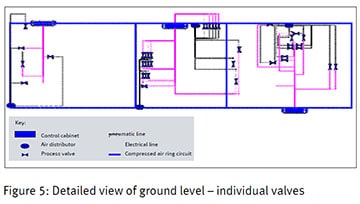
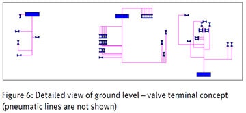
The exact positions of the electrical and pneumatic lines for all the solenoid valves have been determined during a careful on-site inspection, and have been added to a layout drawing. The layout drawing is used to establish the lengths of the various lines. Figures 5 and 6 show detailed views of the ground level with an individual valve concept and a valve terminal solution; a similar procedure has been used for the other levels.
 Calculations have been worked out for four areas:
- Indoor, non-potentially explosive atmosphere
- Indoor, Ex zone 2
- Outdoor, Ex zone 2
- Outdoor, Ex zone 1

The results depicted in figure 7 demonstrate that the valve terminal solution is significantly more cost efficient in all areas. It amounts to savings of between 14% and 42% for product and installation costs. This mathematical model can be used as a point of reference when transferring the results to other systems.
 Reduced compressed air infrastructure for additional savings
The compressed air supply for the system in our example consists of a ring circuit with distributors for each level (see figure 5, lines sketched in blue). This type of installation is typical and is commonly used in precision and specialized chemical systems.
If by using the valve terminal solution the ring circuit with air distributors can be avoided, additional 5-digit savings can be realized when it comes to investment costs. These costs are not taken into account in figure 7.
Cost considerations over the entire lifecycle
The cost comparison only includes investment costs. Additional savings that can be achieved through consistent use of valve terminal technology during the entire lifecycle of the production system have not been taken into consideration. For example, system downtime caused by malfunctions can be avoided through the use of diagnostic procedures or can be significantly reduced by dedicated error location indication.
Advantages during commissioning
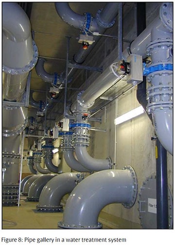
Commissioning is often neglected in the planning phase. Figure 8 shows a typical piping installation for a filter system in a water treatment plant. During dry commissioning of individual valves, the system is completely wired and connected with tubing.
 Compressed air is supplied and the solenoid valves are manually actuated to make sure that the individual valves have been correctly connected. Many of the valves in the system shown here are difficult to access and a ladder is often required. The allocation list cannot be checked on-site.
The situation is similar in figure 9 which shows the pipe gallery of two digestion towers for sludge treatment at a municipal wastewater treatment plant. Many of the pipes and the respective valves are installed just below the ceiling.
In this application, control cabinets with valve terminals have been installed instead of individual valves (figure 10). The control cabinets can be easily accessed by the operators. This means that distances are significantly reduced during dry commissioning. In addition, it is easy to implement a systematic commissioning procedure. The valve position is indicated by limit switches. The signals are connected  to the I/O modules on the left-hand side of the valve terminal. Each input and output signal (e.g. from the solenoid valve as well) is displayed directly by LEDs. If the fieldbus is also active, the programmer can check the signal allocation directly against the process identifiers. An additional advantage offered by valve terminals is the fact that function blocks or parts of the system can be grouped together and represented in the valve terminal. This makes it easier to automate complex systems in a clear, modular fashion and creates greater transparency for the operator.
Transparency is particularly important when an operator has to run several systems or when systems comprise thousands of valves, for example in the pharmaceutical industry.
 A formulation system for a pharmaceutical application can be seen in figure 11. More than 10,000 process valves that come into contact with the media are frequently used in systems of this type, usually in combination with single-acting pneumatic actuators. It is often not possible to directly mount the solenoid valves. Automation using valve terminals is crucial here for economical reasons. If several companies are involved in building a system – which is normal for systems with this level of complexity – it is advisable to standardize the control cabinets with the valve terminals to create transparency for the operator and to achieve cost advantages over the system’s entire lifecycle in terms of warehousing, training of maintenance personnel, etc.
Valve terminals in safety instrumented systems
 More and more existing process automation system and all new ones must be subjected to a systematic safety review in accordance with IEC 61511.
If the HAZOP analysis (hazard and operability) indicates a safety risk for persons who are within or in close proximity to the system, or for the environment, the risk must be reduced to an acceptable level by implementing suitable measures.
The risk can be reduced by using either construction/design or organizational measures. However, precautionary measures must frequently also be implemented in the system’s control system.
Depending on the required SIL, certain system functions must be designed so that their probability of failure is as low as possible. These functions include, amongst others, overfill protection as well as pressure and temperature monitors.
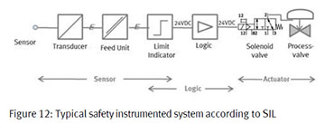 Figure 12 shows a typical SIL circuit consisting of a sensor, a barrier, an input, a safety controller, an output, a further barrier, an ESD solenoid valve (emergency shutdown), and a process valve.
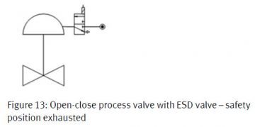
The task of the ESD valves is to safely exhaust the working chambers of the actuators if required. This is intended to ensure that the actuator is advanced to the specified safety position with the help of the spring package. The safety position can be either closed or open depending on the requirements of the process.
 In safety instrumented systems with ratings of up to SIL2, the function of the ESD valve can be integrated into a valve terminal as long as the valve terminal is SIL certified.
Application example: a system for producing pesticides
One of the world’s leading manufacturers of pesticides implemented this concept in its production system. The system is used for the production of active ingredients in pesticides. Roughly 2500 tons are produced each year.
The system consists of various reactors which are automated by approximately 1600 valves. The valves are distributed over about 100 valve terminals. All the control valves are 3/2-way valves which activate numerous types of single-acting actuators. The entire system is designed in accordance with ATEX zone 2.
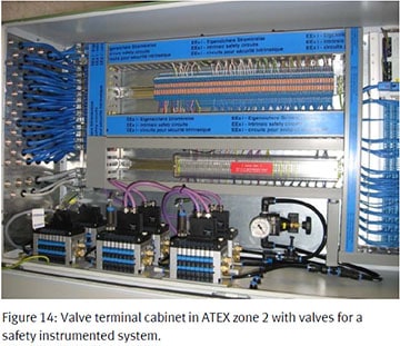 All non-safety-relevant valves communicate with the control system via Profibus DP. All the valves which are part of the safety instrumented system are connected directly to the safety controller’s I/Os via multi-pin cables.
As can be seen in figure 14, the valve terminals connected via Profibus DP and the valve terminals which are connected to the safety controller are installed in a cabinet.
The benefits for the customer:
All non-safety-relevant valves communicate with the control system via Profibus DP. All the valves which are part of the safety instrumented system are connected directly to the safety controller’s I/Os via multi-pin cables.
As can be seen in figure 14, the valve terminals connected via Profibus DP and the valve terminals which are connected to the safety controller are installed in a cabinet.
The benefits for the customer:
- Central installation of all components in a cabinet
- Easier maintenance
- Reliable operation
Festo AG & Co. KG
E-mail: chemicals@festo.com www.festo.com
Brought to you by FESTO, a partner of DIRECTPNEUMATICS.COM
© Copyright 2014, Festo AG & Co. KG