The following content about pneumatic linear slides is from FabCo-Air, a partner of Direct Pneumatics
Pneumatic linear slides are a popular choice for automated industrial applications due to their low-maintenance design, cleanliness, ability to withstand extreme operating conditions and proven reliability. Capabilities range from simple pressing operations to demanding multi-axis robotics applications. And linear slides can be found in a diverse group of applications-including packaging, automotive, robotics, medical imaging and general industrial applications.
The linear slide combines an air cylinder power source with a guide mechanism to support the workload over a precise linear path. Figure 1 displays a slide with two guide shafts attached to a common tool bar. Figure lA combines two linear slides to form a two axis slide.


Given the variety and versatility of slides, it’s often difficult to pick the best one for the job. So how do you decide which model to best use for your application? Before you choose, you should ask yourself these simple questions:
- What are you using it for?
- What environment are you using it in?
- How far does it need to travel?
- How fast does it need to move?
- How often should movement be achieved?
The answers to these questions typically boil down to just four key selection factors: force, load capacity, stroke requirements and operating speed.
FORCE
The best way to control the amount of force your linear slide puts out is through the design of the bore. The larger the bore, the more air is able to get in, allowing pressure to build and create the force. A good rule of thumb for selection is to make sure that the linear slide you would like to use has 25% more force available than the application’s nominal.
Determining the size of the bore requires a simple formula:
Force = PSI x Area (power factor)
It is important to remember that in many models, the power factor is different for the extension and the retraction stroke. In the case of pressing applications, there is a possibility that more force may eventually be required than expected, and the best preventative solution is to use a larger bore with a lower supply pressure. A tandem cylinder or Multi-Power® solution can also be used should you be unable to work with a larger bore. Both tandem and Multi-Power® cylinders use multiple pistons to create low-pressure hydraulics using only shop pressure, adding extra air pressure to increase force.
When it comes to lifting applications, the typical requirement is that the slide has at least twice the output force as the weight to be lifted. Underpowered slides have a tendency to be weak and the load will be jerky, slow and uncontrolled. There are also many applications that require little force, and there is a possibility that the size of the hole will be incorrectly ignored. Bore sizes need to work with the slide to provide enough air to create a smooth, controlled motion. Large bores run the risk of wasting air and therefore wasting energy.
CUSTOM OPTIONS
Sometimes your application demands something entirely new. Beyond the basics. there are options that will allow you to custom tailor your linear slide to best fit the application. Often these include toolbar and tool plate styles. However, one of the most important modifications you could make to your linear slide is the addition of the sensor.

Sensors interface between the electronic controller and the linear slide itself. There are many types of sensors available, the more popular ones being reed or Hall Effect switches, which are actuated by a magnetic piston band on the slide’s air cylinder. Some slide models feature a proximity switch option operated by a moving target on the slide’s motion. With the right engineering know-how, you will be able to construct the exact pneumatic linear slide to suit your application.
Many custom modifications would be difficult to modify once the slide is complete. In this case, the slide’s manufacturer will add the detail for you while assigning the modification a special part number to make ordering and re-ordering quite easy.
LOAD CAPACITY
The load capacity may seem self evident from a review of the linear slide’s specifications, but there are some important things to know when making your choice. For instance, capacity is determined by two factors: the strength of the guideshaft to resist deflection, and the ability of the linear bearing to support the load. While these are the two most basic characteristics, the determination is not always so straightforward.
In fact, the largest category of linear slides in use today employ two or more shafts in the guiding mechanism, where workloads are attached to the reciprocating tool bar, creating an overhung load. On paper, this causes undesirable loading to the leading edge of the linear bearing, but this is often balanced by the fact that most bearings have a much higher load rating than the strength of the guideshafts.

Linear bearings are also rated to support the load, especially in an overhung situation. For example, linear ball bearings can be rated for 20 pounds with a 0.005 deflection on an overhung load, which may sound as though it can’t do the job. However, when all bearings are put together, they have a total load capacity of several hundred pounds, producing the “over-capacity” to assure precision and longevity even in overhung situations.

If you are working with a heavy load, it’s best to use the carriage load configuration. Nevertheless, when it comes to guideshaft style linear slides, carriage loads have a tendency to cause their shafts to deflect or bend on longer strokes. If you attach optional support members to the guideshafts in question, the load capacity will dramatically increase, and deflection can be reduced to less than 0.005 inches on very heavy loads. This way you can use a smaller model with the addition of optional support, avoiding slide models with a prohibitively large diameter guide shaft.
Figures 4A and 48 show optional center support members attached to guide shafts which dramatically increases load carrying capacity.


PACKAGED PNEUMATIC LINEAR SLIDES
Sometimes. performing the many calculations needed to create your ideal pneumatic linear slide can be time consuming. Luckily, for the engineer with time and budget constraints. There are packaged linear slides. With the added bonus of saving on costs. pre-packaged pneumatic linear slides come with everything you need to fit a standard application. Using an off-theshelf component also lowers maintenance and machine repair costs due to standard components having a more universal design.
The concept of pre-packaged pneumatic linear slides is relatively new. Originally, linear slides were conceptualized and manufactured by the equipment builder using a mixture of custom or off-the-shelf components. While the custom components worked extremely well, they ran the risk of being cost-prohibitive. The rise of the packaged linear slide made straightforward linear motion systems easier to construct, with obvious monetary and time benefits on applications that did not require a “reinvention of the wheel.”
STROKE
Stroke is a straightforward factor when selecting your linear slide. Linear slides are often offered in one-inch stroke increments, commonly slightly longer than the application requires for “safety travel.” which allows for a safe stopping time.
You should generally specify a stroke slightly longer than your application requires and make use of the adjustable stops offered as an option on most slides. These hard stops allow you to dial in a stopping accuracy within +/- 0.001 inch.
There are many stop options available, including clamp collars, or a threaded stop bolt/stop nut arrangement as shown below in Figure 3.

OPERATING SPEED
Surprisingly, speed is an overlooked aspect when selecting pneumatic linear slides. Safe speed without external stops is generally six to eight inches per second, but acceleration/deceleration should not be ignored. When it comes to shorter stroke applications, ignoring acceleration and deceleration speed can hurt your entire project. For example, a one-inch stroke in 0.16 seconds measures an average speed of six inches per second, but that is not necessarily true. In reality, the speed is much higher due to acceleration time.
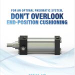
Higher speeds can end in higher impact forces if stopped suddenly at the end of a stroke. This is potentially destructive, but urethane bumpers can be used to cushion such forces if accuracy when stopping is not a concern. Either hydraulic shock absorbers or internal cylinder air cushions can be used for more precise, cushioned stops.
Bearing type and speed are also related. High speeds are best accomplished with linear ball bearings, which can lead to a speed of up to 100 inches per second. However, short stroke fast-reciprocating motions should avoid ball bearings, as inertia tends to make the balls “skid” on the track when suddenly reversed.
By nature of its design, the pneumatic linear slide is ideal for a wide range of uses. Once you understand the fundamental selectors that must be considered during your selection process, choosing your pneumatic linear slides will be easy. By doing the proper research and knowing exactly what you will need to achieve your objective, you will be able to save money, time and aggravation.
QUICK REFERENCE GUIDE TO FABCO-AIR LINEAR SLIDES
Type: “L” & “S” Series (sleeve bearings)
- Description: An inexpensive series using non-repairable air cylinders. The “L” Series is similar to the “EZ” Series while the “S” Series is similar to the “SE”. Note: Sleeve bearings need clearance to operate. Therefore some too/bar play exists. “L” & “S” slides are not intended for ultra-precision applications.
- Reason to Select: The most cost-effective option for lower precision and load bearing applications.
- “S” Series: Shorter than “L”, but less capacity and more “play.”
- “L” Series: High load capacity. Less “play” than “S” because bearings are further apart.
- “S” Series: Shorter than “L”, but less capacity and more “play.”
Type: “GB” Series (sleeve bearings)
- Description: Air cylinder is machined into bearing block. Standard features include bottom, side and rear mounting holes, top and side ports. Toolbar with top, front and bottom mounting holes.
- Reason to select: Rugged block slide, featuring replaceable Duralon• bearings, repairable built-in cylinder, interchangeable bolt pattern. Dual port locations, multiple mounting surfaces. Ten inch stroke or less.

Type: “EZ” Series (linear ball bearings)
- Description: Rugged slide with guide shafts on either side of integral air cylinder. The bearings are spaced further apart as stroke increases, providing exceptional bearing support.
- Reason to select: Wide spacing of guide shafts to resist torsional load. Good load capacity. Provides “no-play” precision motion. Widest choice of tooling, stop and shock options.

Type: “SE” Series (linear ball bearings)
- Description: A shortened version of the “EZ” Series to save length. Cylinder is built into the bearing block which houses four linear ball bearings.
- Reason to select: Shorter than “EZ”. Good load Wide spacing of guide shafts to resist torsional load. Linear ball bearings at each end of bearing block provide “no-play” precision motion.

Type: “TS” Series (linear ball bearings)
- Description: Very compact. It is the only linear ball bearing pneumatic linear slide available that is “built into” the air cylinder.
- Reason to select: Used where space is limited. High load capacity. Linear ball bearings at each end of cylinder provide “no-play” precision motion. Many tooling options available.


