Written by: FESTO
Key considerations for designers looking at bearing systems with linear axes.
The majority of electro-mechanical axis utilize extruded aluminum profiles in a range of sizes with a single guide rail and bearing arrangement driven by an electric motor through a belt or ball screw arrangement. There are physical limitations to the forces such a system can accurately and reliably guide. This paper explores some alternative design arrangements to cope with higher load applications and identifies design considerations observed during the development of a Festo high load, twin rail system.
Introduction
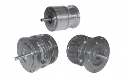
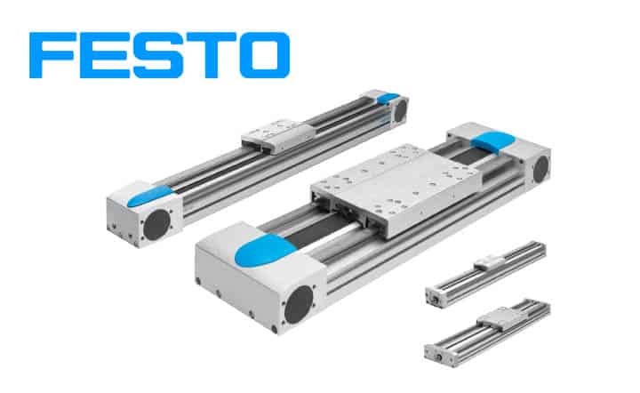
Since 2008, Festo has manufactured a highly successful electromechanical axis [type: EGC Fig. 1]. These comprise of a motor mounting, a spindle or belt screw drive arrangement coupled to a carriage mounted on a bearing guide rail. These elements are mounted within a very rigid aluminum profile designed around a Cupola arch principle [see sidebar page 4]. The bearing types used are caged recirculating ball type [EGC-KF] which are considered to be the best.

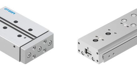
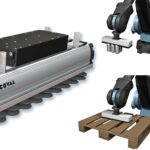
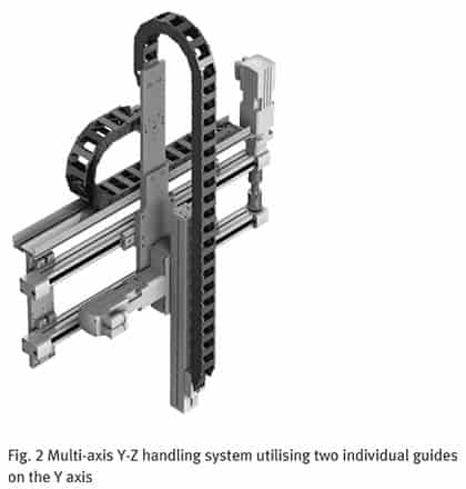
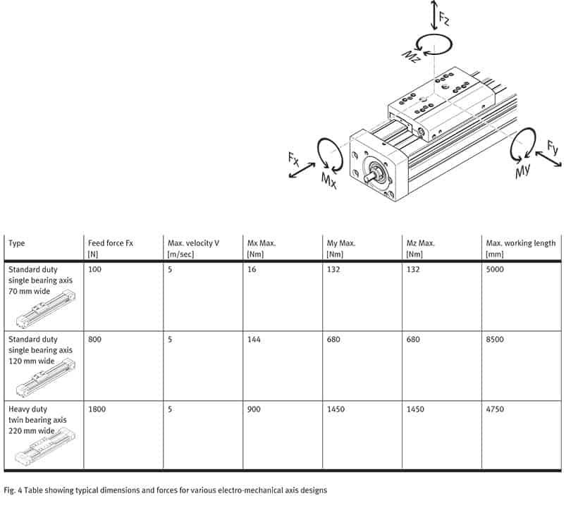
Within the automation market, there are many high load applications where the size of a single profile and bearing arrangement would be too big and expensive. The requirement was therefore identified for a cost-effective, dynamic, and easy to install, high load, guide unit. Typical applications are for use as y-axis in a multi-axis handling system [see Fig. 2 and Fig. 4 of base system requirements – stroke, load, moments].
 Many designers achieve high load capability by utilizing two electro-mechanical guide units in parallel. The distance between the two bearing units considerably increases the ability of the system to resist higher torques. Whilst offering a high degree of flexibility to the designer, this solution is more than twice the cost and the life expectancy of the system is not easy to predict. The designer has to take ownership of establishing the optimum performance layout, as well as adding the additional costs of trying to align the components on a very stiff machine framework, constructing custom coupling plates, driveshafts, etc. The guide arrangement selected must permit loads in all the required directions and deliver the systems required overall lifetime totally without or with pre-determined maintenance. Physically modular kits are available to enable two separate electromechanical axis to be combined but the problem of calculating the eventual performance – accuracy and running life, remains.
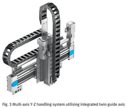
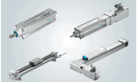
Festo identified the opportunity to offer machine builders a single combined axis solution with a single, wider profile with multiple guide rails to cater for high load applications [type EGC ‘heavy-duty’ or EGCHD for short Fig. 3]. Whilst this seemed a simple task, the reality of developing such a solution proved more challenging than first considered and highlighted some useful insights for design engineers.
Initial designs called for a concept based on the same, very stiff Cupola arch aluminum profile, two guide rails mounted accurately and rigidly as far apart as possible, and the, by now, well-proven caged ball bearing cartridges. The process took over two years and several bearing systems from different suppliers were tested.
 Supporting profile design
To ensure bearing life was maintained in the twin bearing axis, the tolerances were carefully defined for the contact surfaces of the profile with the linear bearing guide rail. It was determined that to deliver a high-performance guide system the supporting aluminum profile would in itself need to be extremely strong, rigid, and accurately produced. To ensure the lifetime of the system the axis needs to be available in lengths up to 9m long, installed with a parallelism of ±0.05mm, and a flatness deviation of less than 0.2mm.
Working extensively with several extrusion manufacturers, it was determined that again using the internal arch principle, it is possible to manufacture a profile to the required stiffness tolerances for the axis, but they were not able to deliver the flat bearing mount surface. Instead, a special machine tool had to be developed to mill the surface of the extrusion where it meets the guide rail on the standard 5.5m, or special order extended9m, profile lengths. Research had shown these profile sizes would cover the majority of customer applications. Although extra machining adds to the overall production costs, this was deemed to outweigh the benefit of a tenfold improvement inaccuracy. The development of such a machine was challenging, as the profiles can weigh 125 kg so again this was a custom development just to suit this product need.
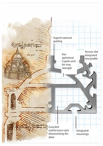 Cupola arch – applied in architecture and now, electrical and mechanical axis Often, manufacturers of mechanical axes will have a very high-quality rail but bolt it to a profile that is not particularly stiff; the result being that the whole structure flexes – similar to having a high-performance car engine bolted onto a chassis that flexes and bends while cornering, thus reducing the overall performance of the car.
For the original standard axis, and during the development of the twin axis system, a very stiff profile was developed using a Cupola arch system – a design pioneered by Da Vinci and utilized extensively by Gaudi. This incredibly stiff profile allowed a rail on the profile so that nothing gives – the axes itself is used as the structural member of the system. Instead of bolting a mechanical axis onto a structural member, with the Cupola arch system, the mechanical axis becomes the structural member – saving considerable weight, as well as assembly time and the associated costs.
Initial test phase
Building on the experience gained from the linear guide used for the standard [EGC] axis, the next step was durability testing. Samples were placed within an endurance test laboratory and cycled at their specified maximum catalog feed force. For these initial tests, three samples were taken for each size with a target endurance life of at least 5 million cycles equating to an estimated 5,000 km. However, after just 500 km of tests, the first failure of the axes unexpectedly occurred – when balls from the bearing cassette were ejected from the housing.
Initially, the design team’s investigation of the failure focused on the linear guide itself and it was decided to repeat the test using the same linear guides but from a different production run. A new
a durability test was started and all too quickly the same poor results were observed.
The investigation focused on the bearing system itself. It is clear that in a dual rail system, the two axes are never completely parallel – there is always some deviation tolerance. In typical systems using two separate but aligned electromechanical axis, the plate connecting the two bearing carriages will compensate for some of this misalignment by deforming to some degree. The issue with the new single Cupola arch system profile was that there is practically no compliance, the structure is so stiff and the bearings were fighting each other, resulting in premature wear and failure; it was determined that this was the root cause of the poor early test results.
Bearing System
During the development phase, the key focus was on the rigidity of the bearing system. In the early trials, the well-proven caged ball system from the existing single-axis system [EGC] was used but as identified, these failed within 500km – not just once but also on a retest.
The linear guide initially selected was identical to the proven design used on the single rail systems, a high performance, and a very stiff solution. In this instance though, the balls and rail in the bearing were not designed to deflect and therefore did not compensate for the alignment tolerances in the dual rail design; hence the failure.
There are many ball bearing arrangements and different bearing manufacturers can select from many variables to optimize their solutions these include, the number and size of balls in contact, their arrangement, contact angles, and how the balls are retained.
Each bearing manufacturer constructs different arrangements; a bearing that has an O-arrangement and ‘caged’ from one manufacturer, for instance, may not necessarily have the same characteristics and performance of a similar type from another manufacturer. This can be due to other design differences, they may have higher or wider dimensions, or the size of balls differ. Effectively, the different combinations of bearing systems available on the market vary widely, and choosing the optimum system can be very complex, a close development relationship with the bearing manufacturer is important.
For the EGC-HD an alternative linear guide bearing system was therefore considered which used bearings with larger diameter balls.
Smaller balls have more points of contact to accommodate the load and offer good stiffness.
Bigger balls mean fewer balls in the bearing cassette and therefore fewer contact points. However, with larger ball sizes, the ball itself can compress slightly, compensating for tiny but important misalignment tolerances; imagine a football pressurized to 10psi, this can be squashed or deflected more easily than a tennis ball at the same pressure. Therefore it was determined bigger ball sizes would minutely deflect and be technically better for this system with incredible inherent stiff-ness and yet tolerances need to be catered for.
In this twin rail system, there are heavy loads therefore bearing ball size has compromises and the optimum size has to be very carefully selected. The rail profile is very stiff so there is very little deflection, all the movement has to be accommodated by the balls themselves. So, the ball size chosen for the twin rail system was slightly larger than the ones used in the single rail axis. In all, different bearing systems from the different suppliers were evaluated. Designers would naturally select a proven solution that has performed reliably for many years but this example shows that sometimes, the wheel really does need to be re-invented to get the correct solution. What works well in one configuration could not be simply ‘cut-and-pasted’ into another.
Fundamental differences between X- and O arrangements
The orientation of the balls inside the bearing housing has a significant impact on the degree of deflection resistance to the linear guide. There are two mounting geometries: face-to-face (X) and back-to-back (O).
In the X-arrangement, the balls make contact with the rail in an inward-facing configuration, creating an ‘X’ pattern inside the rail. This narrow footprint between the center lines of the balls provides stiffness to the guide, thus reducing the guide’s ability to handle the moment, or bending, loads.
For the O-arrangement (see diagram Fig. 15), where there is an outward-facing ball orientation, the footprint between the balls is much wider offering much greater resistance to applied moment-based forces than the X-arrangement, giving the linear guide better rigidity. In summary, the wider overall O-arrangement distributes the forces more evenly within the guide system. In the original linear guide used for the single axis, there were no inherent moment loads to manage, which is why the X-arrangement offered a far superior solution; for the twin rail axis, however, these forces materialized during the test phase. The X-arrangement, in essence, magnified the contact stresses in the guide rail and bearing blocks – a root cause of failure.
Whilst most engineers will assume that caged ball bearings are superior to uncaged, this status quo was challenged when dealing with such high loads. Much of the space inside a caged bearing cartridge is utilized by the cage itself, reducing the space available for actual balls. Uncaged ball bearings offer more space for balls and thus a higher contact area than caged designs and this higher load capacity helps in heavy-duty applications. When using uncaged bearings, the maximum permissible speed of the final system is not as high as one would achieve using caged bearings. However, on an axis capable of carrying a thousand kilos, speed is not the primary consideration!
It was determined that the arrangement of the four ball-chains on the linear guide was a critical factor. The X-arrangement used in the original single axis solution had proven during testing to be too stiff for a twin guide arrangement so instead, an O-arrangement was used. Selecting an uncaged configuration partially compensated for the increased ball size, enabling more balls (more contact area) within the same cartridge size.
Final test phase
Once the design was completed and the new bearing system integrated, 6 months of durability testing recommenced, this time with no failures. After 5,000km no signs of wear were detected so the tests were extended. Even after 10,000km, all was well. It is estimated that the average service life of an axis of this type within a machine is approximately 3,600km, therefore the new design comfortably offered the operational safety margin required.
Lessons to be applied
Whilst a very stiff and accurate profile (frame) is necessary for highly precise applications, the lack of compliance in such a system has to be carefully considered.
Simple linear bearing systems can be accurately modeled and their performance predicted but bearing systems can quickly become complicated and existing computer models cannot factor in all the
variables and accurately predict operating life.
There is no simple selection of the ‘best’ bearing: caged or non-caged, X or O configuration, ball size etc., all have to be determined and paired to the application.
Engineers should factor the choice of guide system used into their overall design, especially in systems that carry large masses and are typically connected to a stiff structure.
Conclusion
For a one-off, special purpose machine designer it wouldn’t be practicable to undertake such an evaluation of the options [time or cost], and the temptation would be to massively over-engineer their solution or risk premature machine failure.
Brought to you by FESTO, a partner of DIRECTPNEUMATICS.COM
© Copyright 2014, Festo AG & Co. KG